TRIAC Dimming for LED Bulbs: Compatibility, Risks & Commercial Applications
Introducción
In commercial retrofits, TRIAC dimming for LED bulbs is one of the most common sources of commissioning delays. Many hotels, office corridors, and retail spaces attempt to reuse legacy TRIAC wall dimmers originally designed for incandescent loads. However, when those dimmers are paired with modern LED drivers, the result is often flicker, audible noise, dropout at low levels, or premature driver failure.
According to the U.S. Department of Energy (DOE), LED lighting systems rely on electronic drivers with non-linear current characteristics, fundamentally different from resistive incandescent filaments. This electrical mismatch is the root cause of most TRIAC LED compatibility problems.
Understanding how TRIAC dimming works—and when it is suitable—can reduce rework costs, protect distributor margins, and improve long-term system reliability.
What Is TRIAC Dimming?
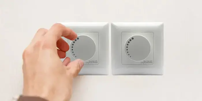
Close-up of a hand adjusting the dial on a sleek white dimmer switch installed on a wall, highlighting intuitive and precise light control.
TRIAC dimming (Triode for Alternating Current) is a phase-cut dimming method that reduces light output by cutting part of the AC waveform.
In simple terms:
TRIAC dimming reduces brightness by shortening the AC waveform delivered to the load.
There are two primary forms:
- Leading-edge (forward phase)
- Trailing-edge (reverse phase)
Electrical Principle of TRIAC Phase-Cut Dimming
In an incandescent system, power follows:
Because incandescent bulbs behave as resistive loads, reducing RMS voltage directly reduces light output proportionally.
LED bulbs, however, do not behave as simple resistors. They contain switch-mode power supplies (SMPS), rectifiers, capacitors, and often power factor correction (PFC) circuits. These components respond differently to phase-cut waveforms.
When TRIAC dimming is applied to LED drivers:
- High dv/dt spikes stress input capacitors
- Inrush currents may exceed 5–10A peaks
- Total harmonic distortion (THD) increases significantly
IEC 61000-3-2 sets harmonic current limits for lighting equipment to protect grid stability1.
Why TRIAC Dimming Causes Flicker in LEDs
Flicker occurs because TRIAC dimming creates fragmented AC cycles. LED drivers attempt to reconstruct DC output from incomplete sine waves, leading to ripple voltage.
IEEE 1789-2015 defines safe flicker limits and modulation thresholds for LED lighting2.
| Parámetro | Incandescent Load | LED Driver Load |
|---|---|---|
| Current Draw | Continuous | Pulsed, non-linear |
| THD Under Dimming | <5% | 100–200% possible |
| Ripple Sensitivity | Bajo | Alta |
| Flicker Risk | Mínima | Elevated at low dim levels |
Low-load conditions (under 20W per channel) are particularly unstable with leading-edge TRIAC dimming.
Leading-Edge vs Trailing-Edge TRIAC Dimming
Understanding the difference is critical for TRIAC dimming for LED bulbs.
| Característica | Leading-Edge TRIAC | Trailing-Edge TRIAC |
|---|---|---|
| Switch Type | TRIAC semiconductor | MOSFET / IGBT |
| Waveform Cut | Rising edge | Falling edge |
| LED Compatibility | Limitado | Significantly better |
| Minimum Load | 20–50W typical | 5–10W typical |
| EMI Generation | Más alto | Inferior |
Trailing-edge dimming produces a smoother voltage transition (lower dv/dt), making it more compatible with capacitive LED driver inputs.
For most commercial LED retrofits, trailing-edge dimmers significantly reduce:
- Flicker complaints
- Zumbido audible
- Sobrecalentamiento del controlador
Measured Causes of Audible Noise in TRIAC LED Systems
Audible hum in TRIAC dimming for LED bulbs typically originates from:
- Magnetostriction in inductors
- High-frequency switching stress
- Harmonic current interactions
IEC 61547 addresses electromagnetic immunity for lighting equipment3.
| Noise Source | Causa | Mitigación |
|---|---|---|
| Inductor vibration | Corriente de rizado | Use ferrite shielding |
| Capacitor stress | High crest factor | Increase ESR stability |
| Commutation spikes | TRIAC switching | Add RC snubber circuit |
Testing in acoustic chambers at 50/60Hz significantly reduces RMA rates in hospitality projects.
Compatibility Testing Standards for TRIAC LED Systems
Reliable TRIAC LED compatibility requires structured testing.
Key standards include:
| Estándar | Propósito | Key Metric |
|---|---|---|
| IEC 61000-3-2 | Harmonics control | THD limits |
| IEEE 1789 | Flicker safety | Modulation depth |
| UL 153 | Thermal safety | Temp rise <75°C |
| ENERGY STAR v2.1 | Dimming compatibility | Flicker & dropout control |
ENERGY STAR provides dimmer compatibility guidance for LED lamps.
Testing should include:
- 0–100% dimming sweep
- 1,000-hour cyclic stress test
- Voltage fluctuation simulation
- Dropout detection below 10% dim level
When Is TRIAC Dimming Still Suitable?

Person adjusting brightness using a rotary dimmer switch in a simple desk lamp setup, with neutral décor elements and soft ambient lighting in the background.
Despite its risks, TRIAC dimming for LED bulbs is still viable in specific scenarios:
Suitable Applications
- Legacy hotel retrofits
- Residential-style commercial corridors
- Loads >10W per channel
- Budget-sensitive upgrades
Less Suitable Applications
- New-build smart buildings
- Large zoned commercial spaces
- Low-load distributed LED systems
- Sensitive medical environments
DOE retrofit studies show that reusing existing dimming infrastructure can reduce retrofit cost by up to 30% when compatibility is validated beforehand.
How to Specify TRIAC Dimming for LED Projects
To avoid compatibility failures, specifications should include:
| Specification Element | Recommended Requirement |
|---|---|
| Tipo de atenuador | Trailing-edge preferred |
| Minimum Load | ≥5W per channel |
| THD | <30% per IEC 61000-3-2 |
| Índice de Parpadeo | <0.08 per IEEE 1789 |
| Certification | UL / ETL listed |
Example RFQ language:
“LED bulbs compatible with trailing-edge TRIAC dimming, tested per IEC 61000-3-2 and IEEE 1789 flicker limits.”
Clear specification reduces:
- Commissioning delays
- Warranty disputes
- Compatibility recalls
- Post-install labor costs
Business Impact of Poor TRIAC LED Compatibility
Failure to properly evaluate TRIAC dimming for LED bulbs can result in:
- 15–20% rework cost overruns
- Increased maintenance visits
- Higher RMA rates
- Delayed occupancy certificates
- Reduced contractor reputation
Conversely, validated compatibility improves:
- System stability
- Lifecycle ROI
- Client satisfaction
- Repeat procurement rates
Conclusión
TRIAC dimming was designed for resistive incandescent loads—not electronic LED drivers. While TRIAC dimming for LED bulbs can still function effectively in controlled retrofit scenarios, compatibility must be validated through proper testing, standard compliance, and dimmer-driver matching.
Trailing-edge dimmers significantly improve TRIAC LED compatibility, reducing flicker, noise, and driver stress. However, for large-scale commercial installations, alternative control systems may offer better scalability and long-term efficiency.
The key is not whether TRIAC dimming works—but whether it is properly engineered for LED systems.
If your project involves:
- Legacy TRIAC infrastructure
- Hospitality retrofits
- Mixed-load circuits
- Large-scale LED conversions
Our engineering team can simulate dimmer-driver interaction in-lab before mass production to verify TRIAC LED compatibility and prevent costly site delays.
Contact us to review your load schedule and ensure your TRIAC dimming system performs reliably from day one.
Notas al pie
-
IEC 61000-3-2 – Limits for harmonic current emissions
https://webstore.iec.ch/en/publication/92799 ↩ -
IEEE 1789-2015 – Flicker Recommendations for LED Lighting
https://standards.ieee.org/ieee/1789/4479/ ↩ -
IEC 61547 – EMC Immunity Requirements
https://webstore.iec.ch/en/publication/67273 ↩