How Driver ICs Enhance LED Stability and Dimming Performance for Businesses
Executive summary: In commercial and architectural lighting, the driver IC is the hidden determinant of stability, flicker performance, dimming precision, and long-term reliability. Selecting and integrating the right IC reduces warranty risk, enables consistent customer experience, and improves tender competitiveness. This guide explains how driver ICs control current, how different dimming methods behave, which parameters matter most, and how to translate lab specifications into field reliability.
Why LED Stability Depends on the Driver IC

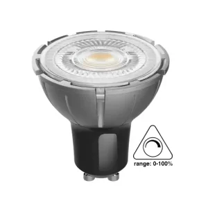
LEDs are current-driven semiconductors—light output tracks forward current, not voltage. Small changes in forward voltage (Vf) from temperature, aging, or bin variance can create large current shifts if the source is voltage-regulated, visibly changing brightness and often color. That is why professional luminaires use constant-current drivers.
“Two popular methods for dimming LEDs … are Pulse-Width Modulation (PWM) dimming and analog dimming.” — Texas Instruments (application notes; see TI technical library)
For stability in B2B products, prioritize driver ICs with:
- Tight constant-current regulation (≤ ±3%; premium parts ≤ ±1%)
- Temperature compensation to counter junction-temperature drift
- Comprehensive protections (over-temperature, open/short, output OVP)
- Well-controlled current ripple, supporting color stability and lifetime
Standards you should align to in professional fixtures include IEC 62384 (electronic control gear performance), IEC 61347-2-13 (LED controlgear safety), and IEC 61000 series for EMC immunity/emissions (harmonics, surge, ESD).
References: IEC 62384, IEC 61347-2-13, IEC 61000 series
Why it matters commercially: In multi-fixture deployments (retail chains, hospitality, offices), stable drivers prevent visible brightness/white-point mismatch between rooms or floors, reducing site callbacks and replacement costs.
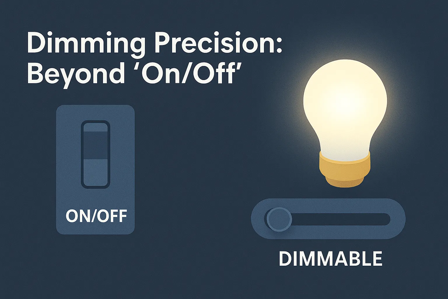
Dimming Precision: Beyond “On/Off” to Human-Centric Quality
Dimming determines perceived quality そして comfort—and increasingly, code and spec compliance. Poor dimming reveals itself as shimmer, banding on cameras, or user-visible steps at the low end.
The two fundamental dimming methods
A. PWM dimming (duty-cycle control).
The LED current amplitude stays constant, but on-time changes. Benefits: excellent color stability そして linearity over wide ranges; compatible with hybrid control. Risks: if PWM frequency is too low relative to exposure or motion, temporal light modulation (TLM) can create perceptible flicker or stroboscopic effects. See IEEE 1789-2015 guidance on safe modulation frequencies and recommended operating areas: IEEE 1789.
B. Analog dimming (amplitude control).
The driver reduces average LED current. Benefits: no high-frequency switching artifact, can be electrically quiet; often efficient at the mid-to-high range. Risks: chromaticity shift at very low current, and limited usable range for tight color applications.
Best practice for architectural/commercial:
Adopt hybrid dimming—analog for mid-range (e.g., 20–100%) and PWM for deep-dim (≤10% to sub-1%). Modern ICs do this internally, preserving color while hitting deep-dim specifications demanded in hospitality, museums, and premium retail.
Design targets for B2B projects
- Dimming range: 100% → ≤1% (premium museum/hospitality: ≤0.1%)
-
Flicker/TLM metrics:
- Percent flicker そして flicker index as legacy indicators
- Pst LM (short-term light modulation) and SVM (stroboscopic visibility) for EU Ecodesign compliance (EU 2019/2020, EU 2019/2015): European Commission – Ecodesign for light sources
- IEEE 1789-2015 for health-based guidance on modulation: IEEE 1789
- Curve feel: perceptually smooth response (log-like curves are often preferred)
- Interface support: 0–10 V, DALI-2, DMX/RDM, Phase-cut (TRIAC/ELV), BLE/Zigbee gateways
Key Driver IC Parameters That Really Matter
| Parameter | What to Spec | Why it Matters in the Field |
|---|---|---|
| Current accuracy | ≤ ±3% (premium ≤ ±1%) | Keeps brightness and CCT consistency across SKUs/batches |
| Current ripple | ≤ 10% (premium ≤ 5%) | Reduces shimmer, improves camera behavior, protects lifetime |
| Efficiency | ≥ 90% (premium 94–97%) | Lowers heat; extends driver and LED lifetime; enables compact housings |
| Dim range & method | 100% → ≤1% (hybrid dimming) | Delivers deep-dim without color shift or steps |
| PWM frequency | High enough for IEEE 1789 recommended regions | Minimizes health risk and visible banding |
| THD & PF | THD ≤ 10–20%; PF ≥ 0.9 | Helps meet DLC/utility programs and building codes |
| Protections | OTP, SCP, OVP, UVLO | Field robustness; fewer RMAs |
| EMC/EMI | Meets CISPR/EN 55015 & IEC 61547 | Market access; prevents interference |
| Interfaces | 0–10 V, DALI-2, DMX, phase-cut, digital | Spec flexibility; retrofit and controls compatibility |
Standards & references:
- Performance/safety: IEC 62384, IEC 61347-2-13
- EMC: CISPR/EN 55015, IEC 61547
- Flicker/TLM: IEEE 1789-2015, EU Ecodesign metrics (Pst LM, SVM)
Analog vs PWM vs Hybrid: A Practical Comparison

| Attribute | Analog Dimming | PWM Dimming | Hybrid (Recommended) |
|---|---|---|---|
| Low-end performance | May show color shift <10% | Maintains chromaticity | Uses PWM low; stable color at deep dim |
| Flicker risk | Low by itself | Depends on frequency | Managed by high-freq PWM in low range |
| Linearity/feel | Smooth but not always perceptually linear | Linear in duty, perceptual mapping needed | Smooth, perceptual curve across the range |
| EMI/compatibility | Electrically quiet | Requires careful layout/filtering | Balanced, with proper layout |
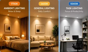
| Best use cases | Task, general office | Stage/retail with deep-dim | Premium retail, hospitality, museums, offices |
Regulatory reminder: If you sell into North America with performance programs (ENERGY STAR®, DLC), review driver PF/THD, efficacy, and flicker guidance: ENERGY STAR Lighting, DesignLights Consortium.
From Datasheet to Reality: Reference Designs & What to Verify
A. Efficiency and thermal headroom.
A driver at 95–97% efficiency generates less self-heat, keeping capacitors and MOSFETs within safe limits. Every 10 °C reduction in internal temperature can dramatically extend capacitor lifetime (Arrhenius behavior). See general reliability notes in DOE SSL resources: DOE Solid-State Lighting.
B. Current regulation and ripple.
Bench-test regulation across line/load/temperature, not just at nominal. Verify ripple under worst-case Vf spread and at deep dim levels.
C. Deep-dim verification.
Measure percent flicker, Pst LM, and SVM under real control scenarios (0–10 V, DALI scenes, phase-cut dimmers). Use compliant instrumentation (per IEC TR 61547-1 for light flicker measurement approaches; EU Ecodesign test methods).
D. Surge and immunity.
Commercial projects routinely face line disturbances. Validate immunity against IEC 61000-4-2/3/4/5/6 (ESD, EFT/burst, surge, conducted RF). Keep surge (±kV) targets consistent with application (e.g., outdoor facades vs. indoor shops).
E. Camera behavior.
Retail and broadcast spaces increasingly demand camera-friendly lighting. Confirm no visible banding with common shutter speeds if PWM is used.
Tip: If your application includes tunable white or dynamic scenes, insist on hybrid dimming and closed-loop current control to preserve Duv and CCT tracking.
Layout, Thermal, and EMI: Integration Tips That Prevent RMAs
Even the best IC can fail in the field without disciplined integration.
- Sense path discipline: Keep current-sense traces short, symmetrical, and away from switching nodes; use Kelvin connections.
- Grounding strategy: Star-ground power and signal returns; avoid current loops under the sense network.
- Snubbers and gate control: Tune to reduce ringing/EMI; validate on an assembled luminaire, not just the demo board.
- Thermal interface: Provide low-theta paths from hot components to housing; verify with thermography in an enclosed can or ceiling plenum.
- Creepage/clearance: Follow IPC-2221 for PCB layout and spacing guidance in your voltage class: IPC-2221.
- Conducted/radiated EMI: Start with common-mode chokes and RC snubbers; confirm against CISPR/EN 55015 limits.
- Line quality: In industrial sites, add surge suppression and filtering; harmonics compliance helps with utility programs (PF ≥0.9, THD ≤10–20%).
Controls Compatibility (Phase-Cut, 0–10 V, DALI-2, DMX, Wireless)
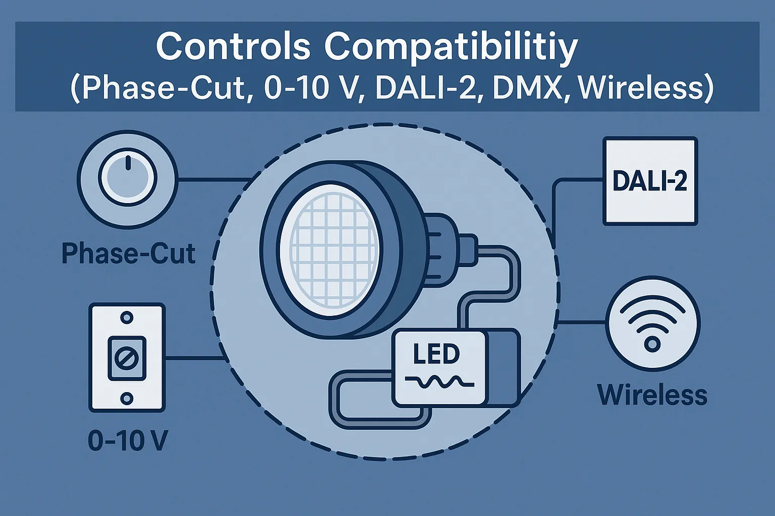
- Phase-cut (TRIAC/ELV): Popular in retrofit markets; choose driver ICs with adaptive algorithms to handle leading/trailing edge variation and minimum load quirks. Always validate the approved dimmer list.
- 0–10 V: Ubiquitous in North America; confirm sink/source behavior and minimum-level accuracy (e.g., true ≤1% not “10% masquerading as 1%”).
- DALI-2: Interoperability and scene control for commercial projects; ensure driver stacks meet DALI-2 certification for luminaires.
- DMX/RDM: Entertainment/hospitality; fast scene changes benefit from hybrid dimming to avoid color shift.
- Wireless (BLE/Zigbee/Thread): Use driver ICs tolerant of control latency and packet jitter; keep in-fixture gateways thermally and RF-isolated from power stages.
Standards references: DALI Alliance, DMX/RDM (ESTA/PLASA), major wireless alliance specs.
Verification Matrix for Specifiers and OEM Buyers
Before freezing a driver IC, run a structured verification that mirrors your real deployment:
| Category | Test | Target / Evidence |
|---|---|---|
| Electrical | Current accuracy vs. line/temp | ≤ ±3% across operating range |
| Dimming | Low-end deep-dim | ≤ 1% (premium ≤ 0.1%) stable; no stepping |
| フリッカー | IEEE 1789, Pst LM/SVM | Within recommended regions; Pst LM ≤1.0; SVM ≤0.9 (EU) |
| EMC | EN 55015, IEC 61547 | Pass margin ≥ 3 dB; surge level per app |
| Thermal | Driver hot-spot in enclosure | < data-sheet limits; capacitor life projection OK |
| Controls | 0–10 V / DALI-2 / phase-cut | No pop-on/pop-off; consistent curve |
| Reliability | HALT/HASS; burn-in | Early failures screened; stable parameters |
| Documentation | Safety & performance | IEC 61347-2-13, IEC 62384 declarations; test reports |
Also align with ENERGY STAR®/DLC program criteria when targeting rebates and utility programs: ENERGY STAR Lighting, DLC.
Business Impact: Why Driver IC Choice Is a Strategic Decision
Lower warranty exposure. Flicker complaints, premature dimming cutoff, or field failures often trace back to drivers. Stabilizing the IC choice reduces RMAs and service truck rolls.
Higher spec win rate. Projects with flicker limits (education, office), deep-dim requirements (hospitality, museums), or camera-critical environments (retail/AV) favor luminaires with proven driver metrics.
SKU simplification. Wide input ranges and multi-mode dimming reduce regional SKUs and ease compliance across markets.
Compliance and incentives. Meeting PF/THD そして flicker criteria opens doors to utility rebates そして public tenders—directly improving price competitiveness.
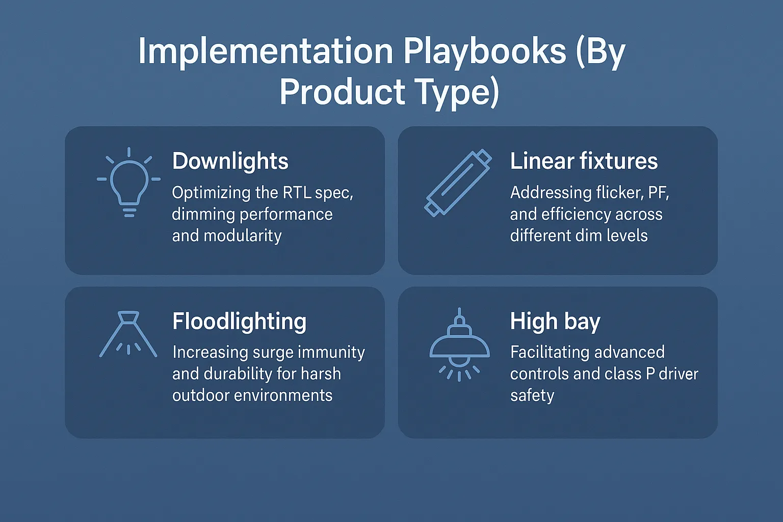
Implementation Playbooks (By Product Type)
Bulbs & retrofit lamps (GU10/MR16/PAR):
- Favor compact, high-efficiency buck/boost-buck drivers with hybrid dimming.
- Validate phase-cut behavior with top dimmer SKUs in target countries.
- Thermal-stress test in sealed cans; derate current as needed.
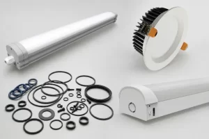
Downlights, panels, troffers:
- Opt for isolated topologies (flyback/LLC) with PF ≥0.9, THD ≤20%.
- Use DALI-2 or 0–10 V variants for enterprise controls.
- Deep-dim verification in large arrays to avoid banding.
High-bay and outdoor:
- Surge robustness (IEC 61000-4-5) and thermal margin are decisive.
- Minimize ripple to protect LED lifetime; specify long-life capacitors.
- Consider programmable drivers for field current tuning.
Common Failure Modes—and How to Prevent Them
- Electrolytic capacitor dry-out from high ripple current and heat → choose 105 °C long-life caps; reduce ripple; improve airflow.
- MOSFET/diode thermal overstress → heatsinking and gate control tuning; verify switching losses at temperature.
- Current-sense drift/noise → Kelvin sensing; shielded routing; precision resistors with low TCR.
- Phase-cut misbehavior (pop-on, dead travel) → adaptive algorithms; dimmer whitelist; minimum load strategies.
- Low-end instability → hybrid dimming; increase PWM frequency; perceptual mapping of the curve.
Quick-Reference Standards & Programs
- Safety & performance: IEC 61347-2-13, IEC 62384
- EMC: CISPR/EN 55015, IEC 61547
- Flicker/TLM: IEEE 1789-2015, EU Ecodesign (Pst LM, SVM): EC Lighting Product Policy
- U.S. programs: DOE SSL, ENERGY STAR®, DLC
結論
The driver IC is not a commodity. It is the control center that governs stability, dimming quality, lifetime, and compliance. For B2B manufacturers and specifiers, choosing ICs with tight current regulation, hybrid deep-dim, low ripple, high efficiency, and robust EMC/EMI immunity transforms hidden electronics into visible product differentiation.
Treat the driver as a strategic component: validate against IEEE 1789 そして EU Ecodesign flicker metrics, certify to IEC 61347-2-13/62384, and prove performance with objective lab data. Your reward is fewer field issues, higher customer satisfaction, and stronger win rates in specification-driven markets.
Ready to engineer stable, flicker-free luminaires?
The Teco Lighting engineering team helps OEMs and integrators select and validate driver ICs for deep-dim performance, low ripple, and global compliance.
👉 Request our LED Driver IC Selection Checklist or contact [email protected] to schedule a design review.