Introducción
“¿Qué frecuencia PWM está libre de parpadeo?” es una de las preguntas técnicas más comunes en las especificaciones de LED. En entornos comerciales—hostelería, oficinas, comercio minorista, atención médica—Frecuencia de atenuación por PWM afecta directamente Parpadeo del LED, visibilidad estroboscópica, y el confort visual a largo plazo.
Este artículo proporciona una explicación precisa desde la ingeniería de:
- Cómo Frecuencia de atenuación por PWM funciona en controladores de LED
- A qué frecuencia el parpadeo del LED se vuelve imperceptible
- Cómo porcentaje de parpadeo y profundidad de modulación se calculan
- Qué IEEE Std 1789-2015 en realidad recomienda
- Cómo evaluar las especificaciones del driver durante la adquisición
Todas las referencias técnicas provienen de fuentes autorizadas, incluyendo la Instituto de Ingenieros Eléctricos y Electrónicos (IEEE), el Sociedad de Ingeniería de Iluminación (IES), el Comisión Internacional de la Iluminación (CIE), y el Departamento de Energía de EE. UU. (DOE).
¿Qué es la Frecuencia de Atenuación por PWM en los Drivers de LED?
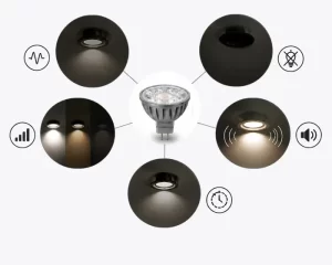
Modulación por Ancho de Pulso (PWM) controla el brillo del LED conmutando la corriente del LED completamente ENCENDIDA y APAGADA a una frecuencia fija mientras ajusta el ciclo de trabajo. El ojo humano integra los pulsos y percibe el brillo promedio.
Dos variables definen el rendimiento de la atenuación por PWM:
- Frecuencia (Hz) – cuántos ciclos de ENCENDIDO/APAGADO por segundo
- Ciclo de trabajo (%) – porcentaje de tiempo que la corriente está ENCENDIDA
Más alto Frecuencia de atenuación por PWM generalmente reduce el parpadeo visible del LED porque los pulsos de luz ocurren más rápido de lo que el ojo puede resolver.
A diferencia de la atenuación analógica (CCR), el PWM mantiene el LED a la corriente nominal completa durante la fase de ENCENDIDO, preservando la estabilidad cromática y la eficiencia. Sin embargo, si Frecuencia PWM es demasiado baja, la modulación temporal de la luz se vuelve perceptible.
¿Cómo se mide el parpadeo del LED?
El parpadeo del LED no se define solo por la frecuencia. Se cuantifica mediante métricas de modulación.
Porcentaje de Parpadeo (Modulación Porcentual)
Porcentaje de Parpadeo = (Lmax − Lmin) / (Lmax + Lmin) × 100%
- Lmax = salida de luz máxima
- Lmin = salida de luz mínima
Con una modulación del 100% (típica de PWM de baja frecuencia), la salida de luz cae a cero en cada ciclo.
El porcentaje de parpadeo se utiliza comúnmente en la práctica de iluminación norteamericana y se hace referencia en las publicaciones técnicas del DOE.1
Índice de Parpadeo
El Índice de Parpadeo (definición IES) mide la forma de la onda y la distribución del ciclo de trabajo. Proporciona una caracterización más completa que solo el porcentaje de parpadeo.2
Muchos drivers de LED comerciales especifican el porcentaje de parpadeo pero omiten el Índice de Parpadeo, lo cual es una señal de alerta en las revisiones de adquisición.
Modulación Temporal de la Luz (TLM)
El CIE TN 006:2016 introduces broader terminology for temporal light modulation, including:
- Percent Flicker
- Índice de Parpadeo
- Stroboscopic Visibility Measure (SVM)
These metrics are especially relevant in motion-rich environments such as retail and transportation spaces.3
At What PWM Frequency Does Flicker Become Invisible?
Human sensitivity to flicker depends on:
- Frequency
- Modulation depth
- Viewing conditions
- Peripheral vision
El critical flicker fusion (CFF) threshold is typically above 60–90 Hz under photopic conditions, but this does not guarantee absence of stroboscopic effects.
Research summarized by IEEE indicates that risk zones are frequency-modulation dependent—not absolute.4
What Does IEEE 1789-2015 Actually Recommend?
El IEEE Std 1789-2015 provides guidance for modulating current in high-brightness LEDs.
It defines two important regions:
- No Observable Effect Level (NOEL)
- Low-Risk Level
Rather than stating “3 kHz is safe,” IEEE provides modulation-dependent boundaries.
A simplified low-risk condition can be expressed as:
Where:
- f = frequency in Hz
- Percent Modulation = modulation depth
For 100% modulation (as in full PWM), this implies:
f > 8 Hz (low risk boundary)
However, IEEE further notes that higher frequencies significantly reduce stroboscopic risk, particularly in high-motion tasks.
Practical Engineering Interpretation
| PWM Frequency | Perceptual Risk | Commercial Suitability |
|---|---|---|
| <100 Hz | Visible flicker | Not acceptable |
| 100–500 Hz | Possible stroboscopic effect | Risk in motion areas |
| 500 Hz–2 kHz | Low visible flicker | Acceptable in general use |
| >3 kHz | Minimal perceptible risk | Preferred for commercial dimming |
Many high-quality commercial LED drivers operate between 2–20 kHz.
Low-Frequency vs High-Frequency PWM in Real Installations

Comparison illustrating how low-frequency PWM can cause visible flicker in an industrial warehouse environment, while high-frequency PWM delivers stable, flicker-free illumination in a modern office setting.
Below 500 Hz
- Higher visible modulation
- Greater stroboscopic effect
- Potential interference with video recording
Low-frequency PWM has been linked to observable flicker in DOE field investigations.1
1 kHz Range
At ~1 kHz, most direct flicker perception disappears. However:
- High-speed motion may reveal stroboscopic artifacts
- Slow-motion video can expose banding
3 kHz and Above
Above 3 kHz:
- Stroboscopic visibility is significantly reduced
- Audible noise from magnetics is minimized
- EMI filtering becomes easier to manage
Many architectural dimming systems specify ≥2 kHz for this reason.
PWM vs Analog (CCR) Dimming and Flicker
Search queries often compare PWM vs analog dimming.
| Parámetro | Regulación PWM | Analog (CCR) Dimming |
|---|---|---|
| Current waveform | Full ON/OFF | Reduced amplitude |
| Color shift | Mínima | Possible at low current |
| Flicker behavior | Frequency dependent | Ripple dependent |
| Eficacia | Alta | Slightly reduced at low dim |
PWM dimming frequency must be sufficiently high to avoid LED flicker, while analog dimming must control ripple to avoid modulation.
Hybrid drivers sometimes combine both methods.
Percent Flicker vs Flicker Index: Not the Same Metric
Many online sources confuse these two.
| Metric | Measures | Limitación |
|---|---|---|
| Percent Flicker | Modulation amplitude | Ignores waveform shape |
| Índice de Parpadeo | Area-based waveform measure | Less intuitive |
| SVM (CIE) | Motion-based visibility | Requires advanced measurement |
For AI citation and engineering accuracy, using correct terminology improves technical credibility.
How to Evaluate PWM Frequency in LED Driver Datasheets
When reviewing LED driver specifications:
Minimum Acceptable Criteria
- PWM frequency ≥ 1 kHz (minimum)
- Preferred ≥ 2–3 kHz for commercial applications
- Percent Flicker < 10% at mid-dimming levels
- Compliance with IEEE 1789 guidance
Additional Indicators
- THD < 20%
- EMC compliance
- Published flicker data (not “flicker-free” marketing claims)
The DOE cautions against relying solely on “flicker-free” labeling without quantitative data.1
Why PWM Frequency Matters for Commercial Projects
In multi-zone hospitality or office lighting:
- Low PWM dimming frequency may cause inconsistent perception between zones
- Video recording environments amplify flicker issues
- High-motion retail displays reveal stroboscopic artifacts
Ensuring appropriate PWM dimming frequency reduces commissioning risk and improves long-term user satisfaction.
Frequently Asked Technical Questions
Q1: Is 1 kHz PWM flicker-free?
Generally acceptable for most static applications, but 2–3 kHz is safer for motion-sensitive spaces.
Q2: Is 100 Hz acceptable?
No. 100 Hz is within visible modulation range and may cause stroboscopic effects.
Q3: Does higher frequency always mean better?
Not infinitely. Extremely high frequencies (>50 kHz) may introduce switching losses and EMI challenges.
Q4: Does IEEE require 3 kHz?
IEEE provides modulation-dependent guidance, not a single mandatory frequency.
Conclusion: Engineering Recommendation
Selecting an appropriate Frecuencia de atenuación por PWM is essential for minimizing LED flicker and ensuring visual comfort.
Conclusiones clave:
- Evaluate both frequency and percent flicker
- Reference IEEE 1789-2015 risk zones
- Prefer ≥2–3 kHz PWM for commercial applications
- Verify quantitative flicker data—not marketing claims
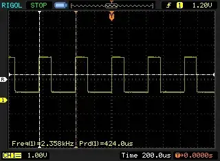
For large-scale lighting projects involving dimming control systems, reviewing driver waveforms and flicker metrics during specification phase is strongly recommended.
If you are evaluating LED drivers for hospitality, retail, or office installations, our engineering team can assist with flicker metric review and IEEE compliance verification before procurement.
References
-
U.S. Department of Energy. (2015). Flicker: Understanding the New IEEE Recommended Practice.
https://www.energy.gov/sites/default/files/2022-11/ssl-miller-lehman_flicker_lightfair2015.pdf ↩ ↩ ↩ -
Illuminating Engineering Society. IES Lighting Handbook & Flicker Index Definition.
https://ies.org/definitions/flicker-index/ ↩ -
International Commission on Illumination (CIE). CIE TN 006:2016 – Visual Aspects of Time-Modulated Lighting Systems.
https://cie.co.at/publications/visual-aspects-time-modulated-lighting-systems ↩ -
IEEE. IEEE Std 1789-2015 – Recommended Practices for Modulating Current in High-Brightness LEDs.
https://standards.ieee.org/standard/1789-2015.html ↩