¿Cómo se fabrican las bombillas LED? Una guía completa desde el diseño hasta la producción en masa
For overseas distributors, importers, and OEM/ODM buyers, understanding how an LED bulb is manufactured is not just a technical interest—it is the foundation of evaluating a supplier’s capability, assessing quality risks, and forecasting delivery reliability. At Tecolite, we manage LED bulb development through a structured, transparent eight-stage workflow that ensures consistency from concept to shipment.
This article outlines every stage of our process, the engineering criteria behind each decision, and the documentation provided to buyers. It serves as a clear reference for procurement teams assessing factory competence and long-term supply stability.
Stage 1 – Concept Definition & Engineering Design
Effective manufacturing begins long before materials reach the production line. The first stage defines the product’s purpose, performance targets, and engineering constraints.

Design Objectives
Each project starts with measurable parameters:
- Lumen output, wattage, efficacy (lm/W)
- CCT options, CRI target, SDCM tolerance
- Beam angle and optical profile
- Voltage range, PF/THD, driver topology
- Mechanical envelope and material limits
- Warranty expectations (typically 2–5 years)
Engineering Analysis
Our mechanical and electronic engineers conduct:
- Thermal simulations to estimate junction temperature under enclosed or open fixtures.
- Optical modeling to test lens geometry and beam distribution.
- Feasibility assessments for tooling, molding shrinkage, and assembly ergonomics.
These evaluations reduce downstream design changes and ensure compliance with IEC/UL safety requirements from day one.
Deliverables to Buyers
- 2D/3D CAD drawings
- Preliminary BOM with alternatives
- Thermal simulation report
- DFM (Design for Manufacturing) notes
This stage enables procurement teams to evaluate whether the design aligns with brand positioning and market requirements.
Stage 2 – Prototyping, Validation, and Engineering Iteration
Prototyping bridges the gap between theoretical design and real performance. At Tecolite, prototypes undergo structured technical evaluations before approval for pilot runs.
Prototype Build
Early samples are produced through:
- CNC-milled heat sinks or bases
- 3D-printed housings for fit and tolerance checks
- Hand-assembled drivers and LED boards
Validation Tests
Each prototype is tested across realistic operating conditions:
- Thermal performance (case temperature, LED junction estimation)
- Optical output (lumen, CCT, CRI, beam uniformity)
- Electrical safety & EMI
- Rendimiento de parpadeo (Pst LM, SVM)
- Compatibility with common dimmers (for dimmable models)
Engineering Adjustments
Test data guides iteration, such as:
- Adjusting MCPCB thickness to reduce thermal resistance
- Rebalancing LED spacing for uniform beam profile
- Optimizing driver tuning for PF/THD targets
This stage typically involves 2–3 prototype rounds before final specification lock.
Buyer Documentation
- Prototype photos and test data
- Revision history
- Technical issue log with resolutions
This provides purchasing teams with visibility before tooling investment.
Stage 3 – Component Qualification & Supply Chain Control
LED bulb performance heavily depends on component quality. Tecolite maintains a strictly controlled supply chain with defined qualification standards.

LED Binning & Qualification
We evaluate:
- LM-80 test data for lumen maintenance
- TM-21 lifetime projections
- Flux, CCT, and Vf bin distribution
- SDCM tolerance over multiple lots
Driver Component Evaluation
Key metrics include:
- Efficiency (≥88% typical)
- Ripple and flicker performance
- Surge protection rating
- Thermal derating behavior
Incoming Quality Control (IQC)
Critical components undergo:
- Visual inspection
- Electrical measurement
- Random sampling with SPC control charts
- Lot traceability registration
Documentation Provided to Buyers
- Approved Vendor List
- IQC inspection records
- LM-80/TM-21 summaries
- Certificates of Analysis for key batches
This ensures long-term stability across repeated production cycles.
Stage 4 – SMT Process and LED Module Construction
SMT (Surface-Mount Technology) is central to LED bulb quality. Controlled reflow profiles and AOI inspection minimize failure rates.
Production Steps
- Solder paste printing with ±10% volume tolerance
- Pick-and-place with ±0.1 mm placement accuracy
- Reflow soldering with controlled thermal curve
- AOI inspection for solder joints and polarity
- Functional testing for LED arrays
Process Controls
- Reflow temperature: 235–245°C
- ESD protection: <100V surface charge
- Copper substrate flatness tolerance: ≤0.7%
LED Module Assembly
LEDs are mounted, bonded, and thermally interfaced to MCPCBs for optimal heat dissipation.
Buyer Outputs
- Reflow profile logs
- AOI defect reports
- SMT lot traceability
This gives buyers confidence that the modules are stable and consistent.
Stage 5 – Driver Integration & Housing Assembly
At this stage, the mechanical and electrical components are combined to form a fully functional LED bulb.
Driver Assembly
Drivers are:
- Potted or mechanically secured
- Inspected for solder quality
- Tested for surge robustness and insulation resistance
Mechanical Housing Assembly
Housing components are:
- Injection-molded with controlled shrinkage
- Fitted to LED modules
- Sealed via ultrasonic welding or screw-lock mechanisms
Thermal & Mechanical Checks
- TIM (Thermal Interface Material) coverage
- Torque verification
- Creepage and clearance compliance
This ensures mechanical strength and long-term reliability.
Documentation for Buyers
- Assembly WI (Work Instructions)
- Torque measurement reports
- BOM finalization
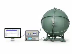
Stage 6 – Optical, Electrical & Reliability Testing
This is the core of Tecolite’s quality assurance. Every batch undergoes full optical and electrical validation.

Pruebas ópticas
Conducted using integrating spheres and goniophotometers:
- Lumen output
- CCT and CRI
- Beam angle distribution
- SDCM consistency
Electrical Testing
Conducted using certified equipment:
- PF (≥0.9 for most models)
- THD (≤15%)
- Surge immunity (1–2 kV depending on market)
- Hi-pot insulation testing
Reliability & Stress Testing
- Burn-in testing for 2–4 hours
- Thermal soak tests in controlled chambers
- Voltage fluctuation tests
- Dimmer matrix testing for compatibility
Documentation Provided
- LM-79 photometric report
- Electrical test summary
- Reliability testing logs
Stage 7 – Packaging, Labeling & Final Inspection
Packaging must protect the product during global shipping while presenting clear branding.

Packaging Process
- Drop test validation
- Vibration simulation
- Label compliance check (CE/UKCA/UL as required)
- Barcode and traceability assignment
Final QA Inspection
AQL inspection (level II) is performed:
- Visual inspection
- Function test
- Safety verification
Buyer Deliverables
- Final inspection reports
- Packaging photos
- Pallet layout plan
Stage 8 – Shipment, Documentation & Post-Delivery Support
Shipping is managed with transparency to avoid delays for overseas buyers.

Logistics Preparation
- CI, PL, and packing list
- BL or AWB
- COA for quality records
- HS code and customs conformity
Post-Shipment Support
- First Article validation support
- RMA handling procedures
- Technical assistance for installation queries
This ensures predictable logistics and stable long-term cooperation.
Conclusión
Reliable LED bulb manufacturing requires disciplined procedures, transparent documentation, and stable process control. Tecolite’s eight-stage framework provides buyers with visibility and confidence—from concept and engineering validation to assembly, testing, and final shipment.
By controlling every detail, we reduce risk, prevent variability, and deliver consistent performance across every batch. For distributors, wholesalers, and OEM/ODM partners, this process is the foundation of dependable supply and long-term partnership stability.