Problemas de Compatibilidad de LEDs MR16: Parpadeo, Fallos y Problemas con Transformadores
Introducción
Los problemas de retroadaptación MR16 en proyectos comerciales rara vez provienen de una sola lámpara defectuosa. En la mayoría de los casos, el mecanismo de fallo se encuentra a nivel del sistema: el comportamiento del transformador existente, la forma de onda del regulador y la respuesta del controlador LED están acoplados eléctricamente, pero se tratan como componentes separados durante la especificación.
Esa brecha crea problemas predecibles en el sitio. Una lámpara puede probarse normalmente en banco pero parpadear en pasillos, no encender en habitaciones de huéspedes o regular erráticamente en salones de baile una vez conectada a la infraestructura halógena heredada. El impacto comercial no se limita al rendimiento visual. Conduce directamente a tiempo de reconfiguración, costos laborales relacionados con el acceso, riesgo de reemplazo por lotes y disputas sobre si la falla está en la lámpara, el transformador o el equipo de control.
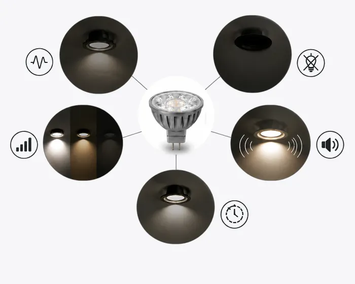
En términos de búsqueda, el mismo problema suele aparecer como "parpadeo LED MR16", "LED MR16 no funciona", "LED MR16 no enciende", "zumbido MR16" o "LED MR16 parpadea con transformador". Estos síntomas suenan diferentes, pero en proyectos de adaptación generalmente apuntan a la misma cadena de compatibilidad.
Para los sistemas MR16, la compatibilidad debe evaluarse como un problema de interacción. La condición eléctrica presentada por la fuente y el atenuador determina la respuesta del controlador; la respuesta del controlador determina la estabilidad operativa del controlador LED; el comportamiento del controlador determina el resultado visible en el sitio.
Resumen Ejecutivo
La mayoría de las fallas de LED MR16 son fallas de compatibilidad a nivel de sistema, no defectos aislados de la lámpara. La baja carga, la distorsión por corte de fase, el desajuste del umbral de arranque y la lógica de protección del controlador crean tres resultados principales: inestabilidad de parpadeo, apagado sin luz y no linealidad de regulación. Las renovaciones estables de MR16 requieren la compatibilidad entre transformador, regulador y controlador de lámpara.
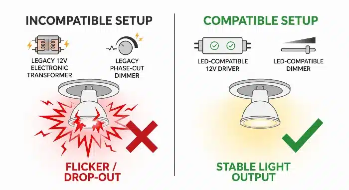
Problemas de parpadeo del atenuador del transformador de compatibilidad LED MR16
Por qué fallan los sistemas LED MR16 en instalaciones reales (no solo a nivel de producto)
En proyectos de renovación, la lámpara suele ser el único cambio visible, pero el entorno eléctrico se hereda del sistema halógeno anterior. Ahí es donde comienzan muchos fracasos comerciales. Un contratista reemplaza lámparas halógenas MR16 de 35 W con lámparas LED MR16 de 5 W, pero el transformador y el regulador permanecen sin cambios. El proyecto parece rentable al principio, pero la puesta en marcha revela rápidamente una operación inestable en diferentes circuitos.
Esto importa porque la falla en el sitio rara vez es uniforme. Una habitación puede operar normalmente mientras la habitación adyacente muestra parpadeo o apagado intermitente, incluso con el mismo SKU de lámpara. Esa inconsistencia aumenta el costo de retrabajo porque la solución de problemas pasa del reemplazo del producto al diagnóstico circuito por circuito.
El modelo de ingeniería útil es simple:
Condición eléctrica -> respuesta del controlador -> comportamiento de la carga -> síntoma visible.
En las adaptaciones MR16, la condición eléctrica está definida por tres factores acoplados:
- características de salida del transformador
- forma de onda del regulador después del corte de fase1
- carga total conectada en relación con la ventana de operación del transformador
La respuesta del controlador proviene del circuito de regulación del transformador y del controlador de la lámpara LED2. A diferencia de las lámparas halógenas, los controladores LED son cargas no lineales3. No consumen corriente continuamente de la misma manera que un filamento resistivo. Como resultado, el transformador puede no regular correctamente y el regulador puede no ver una referencia de carga estable.
El comportamiento de la carga se vuelve inestable:
- los pulsos de voltaje de entrada se vuelven irregulares
- el arranque se repite sin un enclavamiento completo del controlador
- la lógica de protección entra en comportamiento de reinicio de ciclo
- la curva de atenuación colapsa en el extremo inferior
Los síntomas visibles suelen ser de una de tres categorías:
- inestabilidad parpadeante
- sin luz o apagado del sistema
- no linealidad de regulación y desajuste de control
| Condición del Sistema | Respuesta del controlador | Comportamiento de la carga | Síntoma visible del proyecto |
|---|---|---|---|
| Carga del transformador por debajo del rango de operación estable | La regulación de salida del transformador oscila | El controlador LED recarga repetidamente la etapa de entrada | Parpadeo o pulsación aleatoria |
| Forma de onda de corte de fase demasiado estrecha para el arranque del controlador | El controlador no alcanza el umbral de arranque | La lámpara no se engancha | Sin luz después de la retroadaptación |
| Desajuste de respuesta en el extremo inferior entre regulador y controlador | El controlador entra y sale de regulación | La salida se vuelve discontinua | Recorrido muerto, encendido repentino, atenuación deficiente |
Desde una perspectiva de fabricación, la compatibilidad MR16 no puede juzgarse solo por el voltaje nominal y el tipo de base. Para trabajos de retroadaptación comercial, tratamos el transformador, el regulador y el controlador de la lámpara como un sistema operativo y verificamos el comportamiento en condiciones de baja carga y corte de fase antes del lanzamiento. Esa es la única forma práctica de reducir la variabilidad en el sitio.
Problemas de carga mínima del transformador y por qué parpadea el LED MR16
Este es uno de los mecanismos de falla más comunes en instalaciones halógenas existentes. Un circuito originalmente diseñado para varias lámparas halógenas de alta potencia se adapta con lámparas LED MR16 de baja potencia. La carga total cae bruscamente, pero el transformador electrónico original permanece en su lugar. El resultado suele ser un parpadeo inestable que aparece solo después de la instalación completa, no durante una prueba rápida de una sola lámpara.
En hoteles y proyectos minoristas, esto es costoso porque la falla puede surgir solo después de que todos los accesorios estén cerrados, los techos terminados y las escenas de atenuación programadas.
Muchos transformadores electrónicos heredados fueron diseñados para operar por encima de un umbral de carga mínimo4. Las lámparas halógenas naturalmente cumplían ese umbral porque eran resistivas y de relativamente alto vataje. Las lámparas LED MR16 a menudo no lo hacen.
Una vez que la carga total de LED cae por debajo del rango de operación estable del transformador, este puede dejar de mantener una conversión de alta frecuencia continua. El controlador de LED entonces recibe una entrada discontinua u oscilatoria, su bus interno colapsa y se recupera repetidamente, y el usuario ve parpadeo en lugar de una salida de luz limpia.
Esto no es simplemente “el transformador es malo”. Es un problema de estabilidad creado al operar el transformador fuera de su rango de carga previsto. La carga LED es más baja y eléctricamente discontinua, por lo que el bucle de control interno del transformador puede perder regulación.
El comportamiento típico en campo incluye:
- lámparas parpadeando al encender y luego estabilizándose
- brillo continuo bajo condiciones ambientales cálidas
- operación estable con una marca de lámpara pero no con otra
- parpadeo que empeora a medida que más lámparas halógenas son reemplazadas por LED
La solución de ingeniería es la adaptación del sistema:
- verificar el requisito de carga mínima del transformador
- verificar la carga total del canal después de la renovación, no antes
- probar la forma de onda de corriente real de la lámpara-controlador con el transformador previsto
- usar driver de voltaje constante clasificado para LED o reemplazar transformador donde sea necesario
| Característica | Transformador Electrónico Heredado | Controlador de 12 V Compatible con LED | Impacto en Proyecto / Mantenimiento |
|---|---|---|---|
| Dependencia de carga mínima | Generalmente significativa | Típicamente baja o nula | Menos devoluciones de llamada después de una adaptación parcial |
| Respuesta a carga LED no lineal | A menudo inestable | Diseñado para el comportamiento del driver LED | Mejor consistencia de lote en sitio |
| Tolerancia de adaptación | Bajo | Más alto | Menor costo de reconfiguración |
En un patrón típico de puesta en marcha de hotel, las habitaciones de muestra pasan una verificación básica de encendido/apagado durante el día, pero los circuitos de pasillos comienzan a parpadear después de programar las escenas nocturnas. La lámpara no ha cambiado; el punto de operación sí. Si el circuito ya está cerca del límite de carga mínima, un pequeño cambio térmico o de atenuación es suficiente para hacer visible la inestabilidad.
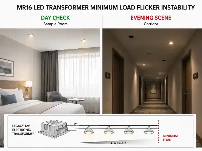
Inestabilidad por parpadeo de carga mínima en transformador MR16 LED
Transformadores Electrónicos vs Magnéticos: Por qué el Comportamiento del MR16 Cambia Completamente
Dos circuitos MR16 pueden estar etiquetados como 12 V, pero el comportamiento de la lámpara puede diferir completamente dependiendo de si la fuente es magnética o electrónica. Esta distinción a menudo se pasa por alto durante las adaptaciones porque los equipos en sitio se enfocan en la potencia de la lámpara y la compatibilidad del portalámparas, no en la impedancia de la fuente y la forma de la onda.
Esa omisión conduce a un rendimiento inconsistente en el mismo proyecto, especialmente en propiedades antiguas donde diferentes pisos fueron renovados en momentos distintos.
Un transformador magnético5 y un transformador electrónico entregan energía de formas fundamentalmente diferentes.
Un transformador magnético generalmente proporciona una salida sinusoidal de baja frecuencia con mayor tolerancia a la variación de carga resistiva, pero puede presentar una mayor corriente de arranque y variación de voltaje bajo carga ligera. Un transformador electrónico genera una salida convertida de alta frecuencia y a menudo depende de una regulación acoplada a la carga.
Con transformadores electrónicos, una carga baja de LED o una entrada de rectificador incompatible pueden hacer que la regulación del convertidor sea inestable. La forma de onda de salida se distorsiona o cicla, y el controlador LED puede no mantener un bus de CC estable. El resultado suele ser parpadeo, pulsaciones o falta de arranque.
Con transformadores magnéticos, el problema es diferente. La salida de CA de frecuencia de línea, la variación de línea, la rectificación de la lámpara y el filtrado del controlador interactúan más directamente. Eso puede aumentar la corriente de rizado en la entrada del controlador y manifestarse como problemas de atenuación en el extremo inferior o modulación visible, especialmente cuando el controlador de la lámpara tiene un margen de filtrado limitado.
Por eso, una lámpara LED MR16 que funciona aceptablemente en un transformador magnético puede fallar en un transformador electrónico, o viceversa. La lámpara no está operando en el mismo sistema eléctrico.
| Característica | Transformador Electrónico | Transformador Magnético | Impacto en Proyecto / Mantenimiento |
|---|---|---|---|
| Naturaleza de la salida | Salida convertida de alta frecuencia | Salida de CA de baja frecuencia | Perfil de estrés del controlador diferente |
| Sensibilidad de carga mínima | A menudo alto | Generalmente menor | Mayor riesgo en retrofit con unidades electrónicas |
| Variabilidad de compatibilidad con LED | Alta | Medio | Se requiere más verificación del sitio |
| Interacción de atenuación | Often unpredictable with legacy dimmers | Depends on primary-side dimming method | Higher commissioning time if unspecified |
For qualification testing, magnetic and electronic transformer groups should be separated. Combining them into one “12 V compatible” claim is technically weak and usually leads to field disputes.
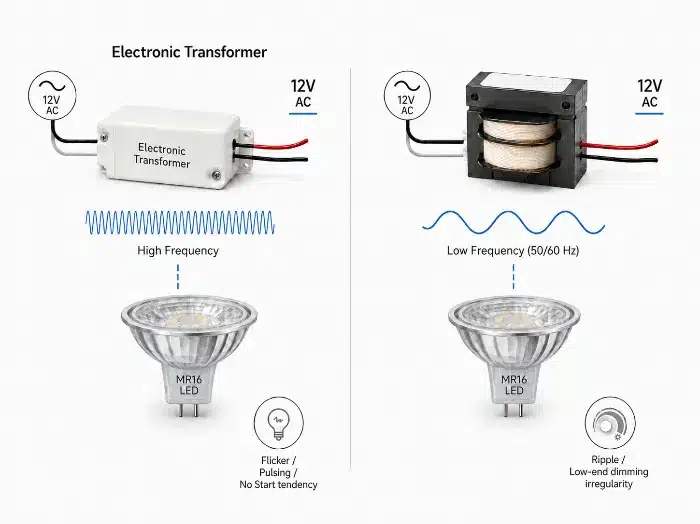
MR16 electronic vs magnetic transformer compatibility
Dimming Incompatibility in MR16 Systems (Phase Cut and Low-End Failure)
Dimming complaints in MR16 retrofits are often reported as “flicker,” but the failure mode is different. In many commercial sites, the lamp turns on and generally works, but the dimming curve is unusable: no response over part of the slider range, sudden pop-on, dropout near low level, or unstable scene recall.
This matters in hospitality and architectural projects because the problem is no longer simple illumination. It directly affects ambience control, scene consistency, and handover quality.
Phase-cut dimming1 was developed around halogen behavior. The dimmer expects a load with broadly predictable conduction. LED MR16 lamps present a driver front end with rectification, energy storage, startup threshold, and protection logic. The result is not a smooth analog reduction, but a sequence of threshold events.
As the phase-cut waveform reduces conduction angle, the available input energy per half-cycle may fall below the driver’s startup or hold-up threshold.6 The driver then moves in and out of regulation instead of following the dimmer smoothly. On site, that becomes low-end failure, pop-on, dead travel, or dropout.
This must be distinguished from random flicker. Here, the issue is control mismatch, not general instability.
Typical dimming incompatibility symptoms:
- lamp stays off until dimmer reaches a high point, then turns on suddenly
- lamp dims normally from 100% to 30%, then drops abruptly
- multiple lamps on the same circuit track differently at low end
- scene settings are not repeatable after power cycling
The engineering response should focus on:
- dimmer type verification: leading-edge7 vs trailing-edge8
- driver low-end hold-up capability
- startup threshold under chopped waveform
- total channel load seen by the dimmer
- whether the transformer itself alters the phase-cut waveform before it reaches the lamp
| Característica | Legacy Halogen Phase-Cut System | MR16 LED-Compatible Dimming System | Impacto en Proyecto / Mantenimiento |
|---|---|---|---|
| Load assumption | Resistive, high wattage | Non-linear, low wattage | Lower complaint rate with matched system |
| Low-end dimming behavior | Typically smooth | Depends on driver threshold design | Fewer scene-setting failures |
| Multi-lamp tracking | Generally consistent | Can diverge if drivers vary | Better batch performance with tighter validation |
In large hospitality projects, the low end is where most complaints happen. Full output often looks acceptable during a fast site check, but once designers demand stable 5% to 20% ambience scenes, incompatibility becomes visible immediately. That is why low-end verification must be part of approval testing.
Why MR16 LED Bulbs Fail to Turn On After Retrofit Installation
A common retrofit failure is simple and disruptive: the new MR16 LED lamp is installed, but nothing happens. The original halogen lamp worked. Voltage appears present. The replacement lamp may even work on another circuit. This creates avoidable confusion during installation and often leads to unnecessary lamp returns.
In commercial fit-out work, repeated no-light events slow teams down because electricians begin swapping lamps, transformers, and dimmers without a clear fault model.
No-light shutdown is typically a startup-threshold conflict, not an immediate product failure.
In this failure mode, reduced conduction angle, low available load energy, or unstable transformer output prevents the driver input capacitor from charging to the startup threshold. The control IC never enters sustained operation, so protection or restart logic repeats without full output. To the installer, the lamp simply appears dead.
This can happen under several conditions:
- dimmer set too low at startup
- electronic transformer not latched because total load is insufficient
- lamp driver designed for cleaner input waveform than site provides
- multiple components each consume part of the available startup window
The key point is that startup and steady-state operation are not the same. A lamp may need a certain energy threshold to turn on, then require less energy to stay on. In retrofits, the system may fail before reaching that initial threshold.
Practical engineering checks include:
- start-up test at multiple dimmer positions
- cold-start and warm-start verification
- minimum and maximum lamp count per transformer
- measurement of effective waveform at the lamp input, not only nominal 12 V output
- compatibility screening across likely transformer families used on site
Startup robustness is one of the most underestimated validation items. A lamp that operates after bench energization may still fail real-site turn-on if the field waveform rises slowly, is phase-cut, or is delivered through a marginal transformer under low load.
Flickering vs Failure: Understanding Different MR16 Failure Modes
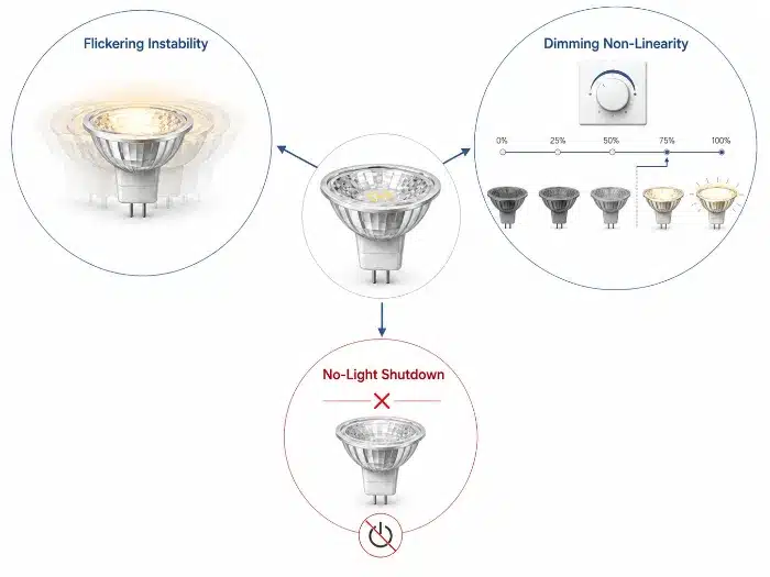
Many site reports group all complaints under “flicker,” but that is technically inaccurate and slows corrective action. A flickering lamp, a lamp that never turns on, and a lamp with poor dimming response are different failure modes with different root causes. Treating them as one category usually results in repeated part changes without resolution.
For contractors and distributors, correct failure classification reduces argument between supply chain parties and speeds up containment.
MR16 compatibility problems should be separated into three system-level modes:
1. Flickering instability
This usually starts with a low-load or distorted supply condition. The transformer or driver regulation becomes unstable, output current varies repeatedly, and the visible result is shimmer or pulsing. Typical triggers include minimum-load conflict, oscillating electronic transformers, and ripple sensitivity.
2. No-light system shutdown
Here, available input energy stays below the startup threshold. The driver does not latch into stable operation, so protective restart repeats or stays inhibited. Typical triggers include startup-threshold mismatch, insufficient conduction angle, and a transformer that never fully latches.
3. Dimming non-linearity
This appears when phase-cut control reduces the usable input window and the driver exits stable regulation at low level. Output no longer follows control proportionally, so the user sees dead travel, dropout, or pop-on. Typical triggers include dimmer-driver mismatch, insufficient hold-up margin, and weak low-end control design.
| Failure Mode | Primary Electrical Trigger | System Response | Visible Symptom | Corrective Direction |
|---|---|---|---|---|
| Flickering instability | Low load or unstable regulation | Cycling input/output | Shimmer, pulsing | Replace or re-match transformer/driver |
| No-light shutdown | Startup threshold not reached | No latch-on | Lamp remains off | Improve startup compatibility |
| Dimming non-linearity | Phase-cut low-end mismatch | Loss of proportional control | Dropout, pop-on | Re-match dimmer and driver |
During field review, the first step should be failure-mode separation, not product replacement. Once the symptom is classified correctly, the electrical chain becomes much easier to trace and the corrective action becomes faster.
MR16 failure modes flicker no light dimming mismatch
MR16 Retrofit Mistakes in Commercial Lighting Projects
Most recurring MR16 project issues are created during retrofit decision-making, not during final commissioning. The common pattern is straightforward: lamp substitution is approved as a one-for-one replacement, while the legacy dimming and transformer architecture is left unverified.
That approach may work in a sample room, but it often breaks down at project scale where batch variation, circuit diversity, and access constraints become significant.
Typical commercial retrofit mistakes include:
- checking lamp fit and beam only, without validating transformer type
- assuming all 12 V transformers are functionally equivalent
- ignoring dimmer model and phase-cut method
- testing one circuit and extrapolating to the entire building
- mixing lamp brands or production batches on one dimmed circuit
- approving on/off function without low-end dimming validation
- failing to document minimum and maximum lamp counts per circuit
Each of these mistakes weakens system control.
The underlying pattern is usually the same: the site audit is incomplete, incompatible legacy control remains in place, the lamp driver sees unstable or unsuitable input conditions, and visible performance varies from circuit to circuit.
Commercial retrofit discipline should include:
- site survey of transformer family and dimmer type
- grouping of circuits by electrical architecture, not by room name alone
- pilot test on representative worst-case circuits
- validation under minimum lamp count and low-end dimming
- batch control for the approved lamp version
In large retrofit projects, the worst failures usually come from mixed infrastructure. One area may contain magnetic transformers, another electronic transformers, and a third a later-generation dimmer. Without circuit classification, even a good lamp design will appear inconsistent because it is being asked to solve multiple incompatible environments at once.
How to Design a Stable MR16 System (Driver + Transformer + Dimmer Matching)
A stable MR16 system is not achieved by selecting a “compatible lamp” in isolation. Stability comes from defining the operating window of the complete channel. That is especially important in hospitality and commercial work, where maintenance access is costly and dimming performance is part of the visual standard.
If this matching work is skipped before procurement, the same budget saved on hardware is usually spent later on recommissioning and replacements.
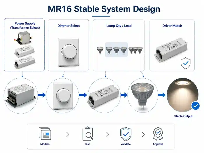
A stable MR16 system requires compatibility across four checkpoints:
Supply type
Identify whether the source is magnetic transformer, electronic transformer, or LED driver replacement.Load window
Confirm minimum and maximum load per channel, including partial failure and staged retrofit conditions.Control waveform
Confirm dimmer type, conduction range, and whether the transformer distorts the waveform delivered to the lamp.Driver operating thresholds
Verify lamp startup threshold, hold-up behavior, protection logic, and low-end dimming stability.
The full system should be validated in a realistic sequence: apply the expected input condition, measure transformer and dimmer response, observe lamp-driver current and voltage behavior, and confirm visible output stability.
Recommended project process:
- collect actual transformer and dimmer models
- define lamp quantity per circuit
- test across expected mains tolerance and temperature range
- validate cold start, warm start, full load, and minimum load
- check dimming repeatability, not just dimming range
- lock approved batch after validation
| Design Checkpoint | What to Verify | Risk if Ignored | Impacto comercial |
|---|---|---|---|
| Tipo de transformador | Magnetic or electronic behavior | Unstable operation | Rework and troubleshooting time |
| Channel load | Minimum and maximum lamp count | Flicker or no start | Room-by-room inconsistency |
| Tipo de regulador | Leading-edge or trailing-edge | Low-end failure | Scene quality complaints |
| Lamp driver thresholds | Startup and hold-up behavior | Shutdown or dropout | High maintenance call rate |
Compatibility claims should be based on a defined test matrix, not assumption. For project business, the intended transformer and dimmer schedule should be supplied before final approval so the system can be simulated under realistic electrical conditions.
MR16 stable system design transformer driver dimmer matching
When to Replace MR16 Systems with Integrated LED Solutions
There are cases where continued MR16 retrofit effort is no longer economically sound. If the project contains aging transformers, mixed dimming hardware, poor access ceilings, or strict low-end scene requirements, repeated compatibility tuning can cost more than replacing the architecture entirely.
For contractors and asset managers, this becomes a lifecycle decision rather than a lamp-selection issue.
Replacement with integrated LED luminaires or dedicated LED drivers should be considered when:
- existing transformer population is mixed or undocumented
- low-end dimming below approximately 10% is required consistently
- repeated lamp changes have not resolved instability
- ceiling access makes future maintenance expensive
- batch consistency across many circuits is essential
- project standardization is more valuable than keeping the MR16 socket format
The decision is commercial as much as electrical. When legacy architecture contains too many compatibility variables, each retrofit attempt carries uncertainty. Over time, the cost of repeated maintenance and commissioning can make an integrated solution the lower-risk choice.
Integrated LED solutions remove several unstable interfaces:
- no separate MR16 lamp-driver variation
- no legacy halogen transformer dependency
- better control over dimming electronics at luminaire level
- simpler standardization across project zones
| Característica | MR16 Retrofit on Legacy Infrastructure | Integrated LED Solution | Impacto en Proyecto / Mantenimiento |
|---|---|---|---|
| Use of existing transformers | Sí | No | Retrofit cheaper upfront, riskier later |
| Control of system compatibility | Limitado | Más alto | Better long-term stability with integrated design |
| Maintenance complexity | Más alto | Inferior | Reduced fault tracing over project life |
| Batch consistency across zones | More difficult | Easier | Lower operational risk |
In large hospitality projects, once the electrical ecosystem becomes too fragmented, staying with MR16 is often a false economy. If multiple rounds of compatibility correction are already expected, moving to an integrated LED platform is usually the cleaner engineering decision.
MR16 replacement integrated LED solution commercial retrofit
Common MR16 LED Troubleshooting Questions
Why is my MR16 LED flickering after replacing halogen?
The most common causes are transformer minimum-load mismatch, electronic transformer instability, dimmer incompatibility, or a lamp driver that cannot remain stable under the existing waveform. The first check should be the transformer model and total connected LED load, not only the lamp itself.
Why does my MR16 LED not turn on even though the old halogen lamp worked?
Halogen lamps draw enough current to keep many legacy transformers active. A low-wattage MR16 LED may not reach the transformer’s operating threshold or the lamp driver’s startup threshold, so the circuit may show voltage but still fail to produce light.
Why does my MR16 LED buzz or make noise?
Buzzing can come from the dimmer, transformer, or lamp driver when the electrical waveform is unstable. It is often worse with incompatible phase-cut dimmers, overloaded or underloaded transformers, or mixed lamp types on one circuit.
Can MR16 LEDs work with old transformers?
Sometimes, but not automatically. Compatibility depends on transformer type, minimum load, output waveform, dimmer type, lamp-driver design, and the number of lamps on each circuit. Commercial projects should test representative circuits before bulk replacement.
Should I replace the transformer or change the MR16 LED bulb?
If the issue appears on one lamp only, check the lamp and socket first. If the same symptoms appear across a circuit or room type, the transformer, dimmer, and load condition should be reviewed before replacing lamps repeatedly.
Conclusion: Business Value
MR16 LED compatibility issues are fundamentally system-engineering failures, not simple lamp defects. The visible symptoms – flicker instability, no-light shutdown, and dimming non-linearity – are produced by interaction between transformer operating limits, phase-cut control behavior, startup thresholds, and driver protection logic.
For commercial projects, the practical objective is clear: reduce uncertainty before installation. Proper system matching improves reliability, lowers maintenance effort, and reduces lifetime cost by preventing repeated site diagnosis, unnecessary replacements, and inconsistent room-to-room performance.
B2B Engineering Recommendation
For MR16 retrofit projects, collect the transformer model, dimmer type, lamp quantity per circuit, target dimming range, and failure symptom before approving bulk replacement. For bulk MR16 retrofit projects, compatibility review should be done before replacing lamps across all rooms or circuits. TECO can help project buyers review whether the issue points to minimum-load mismatch, transformer behavior, dimmer compatibility, or lamp-driver startup limits before recommending MR16 LED products or a broader lighting fixture replacement strategy.
Notas al pie
Phase-cut dimming: a control method that reduces delivered power by cutting part of each AC waveform, commonly implemented as leading-edge or trailing-edge dimming. PNNL’s DOE GATEWAY report explains why LED phase-cut dimming depends on dimmer, driver, and load compatibility. See PNNL: Dimming LEDs with Phase-Cut Dimmers. ↩ ↩
LED driver: the internal electronic circuit that converts incoming electrical power into controlled current or voltage suitable for LED operation. In MR16 retrofits, the driver must operate through the transformer and dimmer environment, not only under clean bench power. ↩
Non-linear load: a load whose current draw does not follow the input voltage proportionally across the waveform. Analog Devices explains that MR16 LED lamps and halogen MR16 lamps draw current differently, which can prevent stable operation with many electronic transformers. See Analog Devices: MR16 LED Driver Compatibility. ↩
Minimum load threshold: the lowest connected load at which a transformer or dimmer can regulate and operate correctly. DOE guidance on LED MR16 replacement lamps notes that low LED wattage may not meet the minimum-load requirement of transformers designed for halogen MR16 lamps, causing shutdown or flicker. See DOE: LED MR16 Lamps. ↩
Magnetic transformer: a conventional iron-core transformer that converts voltage through electromagnetic induction at line frequency. Its behavior differs from high-frequency electronic transformers, so MR16 LED compatibility should be evaluated by transformer type rather than voltage label alone. ↩
Hold-up threshold: the minimum stored energy or input condition required for a driver to remain in stable operation between waveform interruptions. ↩
Leading-edge dimming: a phase-cut method that removes the front portion of each AC half-cycle, commonly associated with triac-based dimmers. NEMA SSL 7A addresses phase-cut dimming compatibility requirements for LED systems. See NEMA SSL 7A phase-cut dimming compatibility summary. ↩
Trailing-edge dimming: a phase-cut method that removes the end portion of each AC half-cycle, typically offering better compatibility with electronic LED loads. Compatibility still depends on the full chain of dimmer, transformer, lamp driver, load count, and wiring conditions. ↩