MR16 LED兼容性问题:闪烁、故障与变压器问题
引言
商业项目中MR16改造问题很少源于单个有缺陷的灯具。大多数情况下,故障机制存在于系统层面:现有变压器行为、调光器波形与LED驱动器响应在电气上耦合,但在规范制定时被视作独立组件。.
这一差距导致了可预见的现场问题。灯具可能在测试台上表现正常,但在走廊中闪烁,在客房中无法启动,或在连接到传统卤素基础设施后在宴会厅中调光不稳定。商业影响不仅限于视觉表现。它直接导致重新调试时间、与访问相关的劳动力成本、批量更换风险,以及关于故障是源于灯具、变压器还是控制装置的争议。.
在搜索术语中,相同问题常表现为"MR16 LED闪烁"、"MR16 LED不工作"、"MR16 LED不亮"、"MR16嗡嗡声"或"MR16 LED与变压器一起闪烁"。这些症状听起来不同,但在改造项目中,它们通常指向相同的兼容性链。.
对于MR16系统,兼容性必须作为一个交互问题来评估。电源和调光器呈现的电气条件决定了控制器的响应;控制器的响应决定了LED驱动器的工作稳定性;驱动器的行为决定了现场的可见结果。.
执行摘要
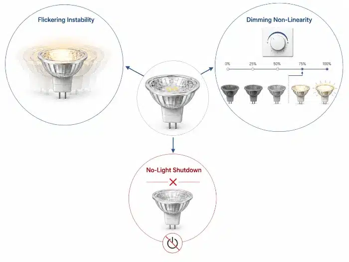
大多数MR16 LED故障是系统级兼容性故障,而非孤立的灯具缺陷。低负载、切相失真、启动阈值不匹配和驱动器保护逻辑导致三种主要结果:闪烁不稳定、无光关闭和调光非线性。稳定的MR16改造需要变压器、调光器和灯驱动器的匹配。.
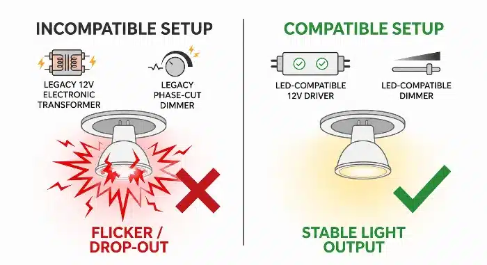
MR16 LED兼容性变压器调光器闪烁问题
为什么MR16 LED系统在实际安装中失败(而不仅是在产品层面)
在改造项目中,灯具通常是唯一可见的变化,但电气环境是从先前的卤素系统继承而来的。这正是许多商业失败的起点。承包商将35W卤素MR16灯具替换为5W LED MR16灯具,但变压器和调光器保持不变。项目起初看起来成本效益高,但调试很快揭示了不同电路上的不稳定运行。.
这一点很重要,因为现场故障很少是均匀的。一个房间可能正常运行,而相邻的房间却出现闪烁或间歇性关闭,即使使用相同的灯具SKU。这种不一致性推高了返工成本,因为故障排查从产品更换转变为逐电路诊断。.
实用的工程模型很简单:
电气状况 -> 控制器响应 -> 负载行为 -> 可见症状。.
在MR16改造中,电气条件由三个耦合因素定义:
- 变压器输出特性
- 切相后的调光器波形1
- 总连接负载相对于变压器的运行窗口
控制器响应来自变压器调节电路和LED灯驱动器2. 。与卤素灯不同,LED驱动器是非线性负载3. 。它们不像电阻灯丝那样持续消耗电流。因此,变压器可能无法正确调节,调光器可能无法看到稳定的负载参考。.
负载行为随后变得不稳定:
- 输入电压脉冲变得不规则
- 启动重复但驱动器未完全锁定
- 保护逻辑进入循环重置行为
- 调光曲线在低端崩溃
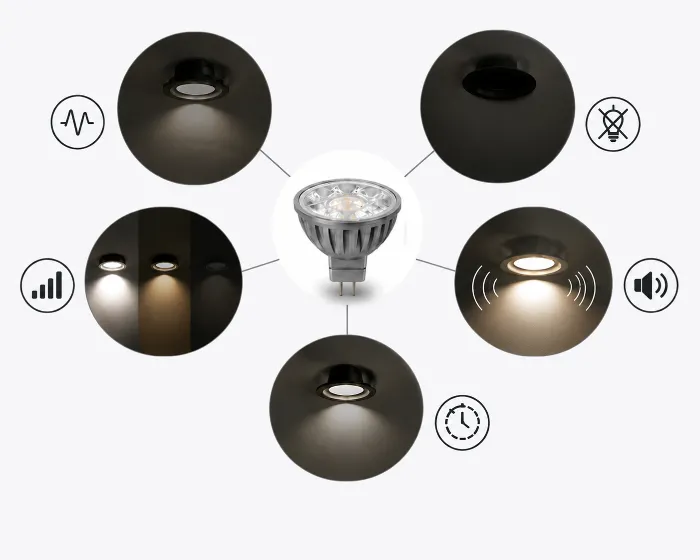
可见症状通常分为三类:
- 闪烁不稳定
- 无光或系统关闭
- 调光非线性与控制失配
| 系统条件 | 控制器响应 | 负载行为 | 可见项目症状 |
|---|---|---|---|
| 变压器负载低于稳定运行范围 | 变压器输出调节振荡 | LED驱动器反复对输入级重新充电 | 随机闪烁或脉动 |
| 切相波形过窄,驱动器无法启动 | 驱动器未能达到启动阈值 | 灯具未锁定 | 改造后无光 |
| 调光器与驱动器低端响应不匹配 | 驱动器在调节状态中反复进出 | 输出变得不连续 | 无行程、突然点亮、调光效果差 |
从制造角度来看,MR16兼容性不能仅通过标称电压和底座类型来判断。对于商业改造工作,我们将变压器、调光器和灯具驱动器视为一个操作系统,并在发布前验证其在低负载和相位切割条件下的行为。这是减少现场变异的唯一实用方法。.
变压器最小负载问题及LED MR16闪烁原因
这是现有卤素安装中最常见的故障机制之一。原本设计用于多个高瓦数卤素灯的电路被改造为低功率LED MR16灯。总负载急剧下降,但原有的电子变压器仍保留在原位。结果通常是仅在完全安装后出现不稳定闪烁,而在快速单灯测试期间不会出现。.
在酒店和零售项目中,这成本高昂,因为故障可能仅在所有灯具封闭、天花板完工且调光场景编程完成后才会显现。.
许多传统电子变压器设计需在最小负载阈值以上运行4. Halogen lamps naturally met that threshold because they were resistive and relatively high wattage. LED MR16 lamps often do not.
Once the total LED load falls below the transformer’s stable operating range, the transformer may no longer maintain continuous high-frequency conversion. The LED driver then receives a discontinuous or oscillatory input, its internal bus repeatedly collapses and recovers, and the user sees flicker rather than a clean light output.
This is not simply “the transformer is bad.” It is a stability problem created by operating the transformer outside its intended load envelope. The LED load is lower and electrically discontinuous, so the transformer’s internal control loop may lose regulation.
Typical field behavior includes:
- lamps flashing at turn-on then stabilizing
- continuous shimmer under warm ambient conditions
- stable operation with one brand of lamp but not another
- flicker becoming worse as more halogen lamps are replaced by LED
The engineering solution is system matching:
- verify transformer minimum-load requirement
- verify total channel load after retrofit, not before
- test actual lamp-driver current waveform with the intended transformer
- use LED-rated constant-voltage driver or transformer replacement where needed
| 特点 | Legacy Electronic Transformer | LED-Compatible 12 V Driver | 项目/维护影响 |
|---|---|---|---|
| Minimum load dependence | Usually significant | Typically low or none | Fewer call-backs after partial retrofit |
| Response to non-linear LED load | Often unstable | Designed for LED driver behavior | Better batch consistency on site |
| Retrofit tolerance | 低 | 更高 | Lower recommissioning cost |
In one typical hotel commissioning pattern, sample rooms pass a basic on/off check during the day, but corridor circuits begin to shimmer after evening scenes are programmed. The lamp has not changed; the operating point has. If the circuit is already near the minimum-load boundary, a small thermal or dimming shift is enough to make instability visible.
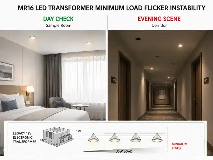
MR16 LED transformer minimum load flicker instability
Electronic vs Magnetic Transformers: Why MR16 Behavior Changes Completely
Two MR16 circuits may both be labeled 12 V, yet lamp behavior can differ completely depending on whether the supply is magnetic or electronic. This distinction is often missed during retrofits because site teams focus on lamp wattage and socket compatibility, not source impedance and waveform shape.
That oversight leads to inconsistent performance across the same project, especially in older properties where different floors were renovated at different times.
A magnetic transformer5 and an electronic transformer deliver power in fundamentally different ways.
A magnetic transformer typically provides a lower-frequency sinusoidal output with higher tolerance to resistive load variation, but it may present higher inrush current and voltage variation under light load. An electronic transformer generates high-frequency converted output and often depends on load-coupled regulation.
With electronic transformers, low LED load or an incompatible rectifier input can make the converter regulation unstable. The output waveform then distorts or cycles, and the LED driver may not maintain a steady DC bus. The result is usually flicker, pulsing, or no start.
With magnetic transformers, the issue is different. Line-frequency AC output, line variation, lamp rectification, and driver filtering interact more directly. That can increase ripple current at the driver input and show up as low-end dimming problems or visible modulation, especially when the lamp driver has limited filtering margin.
This is why an MR16 LED lamp that works acceptably on a magnetic transformer may fail on an electronic transformer, or vice versa. The lamp is not operating in the same electrical system.
| 特点 | Electronic Transformer | Magnetic Transformer | 项目/维护影响 |
|---|---|---|---|
| Output nature | High-frequency converted output | Low-frequency AC output | Different driver stress profile |
| Minimum load sensitivity | Often high | Usually lower | Retrofit risk higher with electronic units |
| LED compatibility variability | 高 | 中等 | More site verification required |
| Dimming interaction | Often unpredictable with legacy dimmers | Depends on primary-side dimming method | Higher commissioning time if unspecified |
For qualification testing, magnetic and electronic transformer groups should be separated. Combining them into one “12 V compatible” claim is technically weak and usually leads to field disputes.
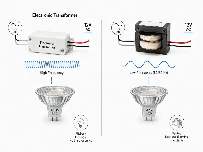
MR16 electronic vs magnetic transformer compatibility
Dimming Incompatibility in MR16 Systems (Phase Cut and Low-End Failure)
Dimming complaints in MR16 retrofits are often reported as “flicker,” but the failure mode is different. In many commercial sites, the lamp turns on and generally works, but the dimming curve is unusable: no response over part of the slider range, sudden pop-on, dropout near low level, or unstable scene recall.
This matters in hospitality and architectural projects because the problem is no longer simple illumination. It directly affects ambience control, scene consistency, and handover quality.
Phase-cut dimming1 was developed around halogen behavior. The dimmer expects a load with broadly predictable conduction. LED MR16 lamps present a driver front end with rectification, energy storage, startup threshold, and protection logic. The result is not a smooth analog reduction, but a sequence of threshold events.
As the phase-cut waveform reduces conduction angle, the available input energy per half-cycle may fall below the driver’s startup or hold-up threshold.6 The driver then moves in and out of regulation instead of following the dimmer smoothly. On site, that becomes low-end failure, pop-on, dead travel, or dropout.
This must be distinguished from random flicker. Here, the issue is control mismatch, not general instability.
Typical dimming incompatibility symptoms:
- lamp stays off until dimmer reaches a high point, then turns on suddenly
- lamp dims normally from 100% to 30%, then drops abruptly
- multiple lamps on the same circuit track differently at low end
- scene settings are not repeatable after power cycling
The engineering response should focus on:
- dimmer type verification: leading-edge7 vs trailing-edge8
- driver low-end hold-up capability
- startup threshold under chopped waveform
- total channel load seen by the dimmer
- whether the transformer itself alters the phase-cut waveform before it reaches the lamp
| 特点 | Legacy Halogen Phase-Cut System | MR16 LED-Compatible Dimming System | 项目/维护影响 |
|---|---|---|---|
| Load assumption | Resistive, high wattage | Non-linear, low wattage | Lower complaint rate with matched system |
| Low-end dimming behavior | Typically smooth | Depends on driver threshold design | Fewer scene-setting failures |
| Multi-lamp tracking | Generally consistent | Can diverge if drivers vary | Better batch performance with tighter validation |
In large hospitality projects, the low end is where most complaints happen. Full output often looks acceptable during a fast site check, but once designers demand stable 5% to 20% ambience scenes, incompatibility becomes visible immediately. That is why low-end verification must be part of approval testing.
Why MR16 LED Bulbs Fail to Turn On After Retrofit Installation
A common retrofit failure is simple and disruptive: the new MR16 LED lamp is installed, but nothing happens. The original halogen lamp worked. Voltage appears present. The replacement lamp may even work on another circuit. This creates avoidable confusion during installation and often leads to unnecessary lamp returns.
In commercial fit-out work, repeated no-light events slow teams down because electricians begin swapping lamps, transformers, and dimmers without a clear fault model.
No-light shutdown is typically a startup-threshold conflict, not an immediate product failure.
In this failure mode, reduced conduction angle, low available load energy, or unstable transformer output prevents the driver input capacitor from charging to the startup threshold. The control IC never enters sustained operation, so protection or restart logic repeats without full output. To the installer, the lamp simply appears dead.
This can happen under several conditions:
- dimmer set too low at startup
- electronic transformer not latched because total load is insufficient
- lamp driver designed for cleaner input waveform than site provides
- multiple components each consume part of the available startup window
The key point is that startup and steady-state operation are not the same. A lamp may need a certain energy threshold to turn on, then require less energy to stay on. In retrofits, the system may fail before reaching that initial threshold.
Practical engineering checks include:
- start-up test at multiple dimmer positions
- cold-start and warm-start verification
- minimum and maximum lamp count per transformer
- measurement of effective waveform at the lamp input, not only nominal 12 V output
- compatibility screening across likely transformer families used on site
Startup robustness is one of the most underestimated validation items. A lamp that operates after bench energization may still fail real-site turn-on if the field waveform rises slowly, is phase-cut, or is delivered through a marginal transformer under low load.
Flickering vs Failure: Understanding Different MR16 Failure Modes
Many site reports group all complaints under “flicker,” but that is technically inaccurate and slows corrective action. A flickering lamp, a lamp that never turns on, and a lamp with poor dimming response are different failure modes with different root causes. Treating them as one category usually results in repeated part changes without resolution.
For contractors and distributors, correct failure classification reduces argument between supply chain parties and speeds up containment.
MR16 compatibility problems should be separated into three system-level modes:
1. Flickering instability
This usually starts with a low-load or distorted supply condition. The transformer or driver regulation becomes unstable, output current varies repeatedly, and the visible result is shimmer or pulsing. Typical triggers include minimum-load conflict, oscillating electronic transformers, and ripple sensitivity.
2. No-light system shutdown
Here, available input energy stays below the startup threshold. The driver does not latch into stable operation, so protective restart repeats or stays inhibited. Typical triggers include startup-threshold mismatch, insufficient conduction angle, and a transformer that never fully latches.
3. Dimming non-linearity
This appears when phase-cut control reduces the usable input window and the driver exits stable regulation at low level. Output no longer follows control proportionally, so the user sees dead travel, dropout, or pop-on. Typical triggers include dimmer-driver mismatch, insufficient hold-up margin, and weak low-end control design.
| 失效模式 | Primary Electrical Trigger | System Response | Visible Symptom | Corrective Direction |
|---|---|---|---|---|
| Flickering instability | Low load or unstable regulation | Cycling input/output | Shimmer, pulsing | Replace or re-match transformer/driver |
| No-light shutdown | Startup threshold not reached | No latch-on | Lamp remains off | Improve startup compatibility |
| Dimming non-linearity | Phase-cut low-end mismatch | Loss of proportional control | Dropout, pop-on | Re-match dimmer and driver |
During field review, the first step should be failure-mode separation, not product replacement. Once the symptom is classified correctly, the electrical chain becomes much easier to trace and the corrective action becomes faster.
MR16 failure modes flicker no light dimming mismatch
MR16 Retrofit Mistakes in Commercial Lighting Projects
Most recurring MR16 project issues are created during retrofit decision-making, not during final commissioning. The common pattern is straightforward: lamp substitution is approved as a one-for-one replacement, while the legacy dimming and transformer architecture is left unverified.
That approach may work in a sample room, but it often breaks down at project scale where batch variation, circuit diversity, and access constraints become significant.
Typical commercial retrofit mistakes include:
- checking lamp fit and beam only, without validating transformer type
- assuming all 12 V transformers are functionally equivalent
- ignoring dimmer model and phase-cut method
- testing one circuit and extrapolating to the entire building
- mixing lamp brands or production batches on one dimmed circuit
- approving on/off function without low-end dimming validation
- failing to document minimum and maximum lamp counts per circuit
Each of these mistakes weakens system control.
The underlying pattern is usually the same: the site audit is incomplete, incompatible legacy control remains in place, the lamp driver sees unstable or unsuitable input conditions, and visible performance varies from circuit to circuit.
Commercial retrofit discipline should include:
- site survey of transformer family and dimmer type
- grouping of circuits by electrical architecture, not by room name alone
- pilot test on representative worst-case circuits
- validation under minimum lamp count and low-end dimming
- batch control for the approved lamp version
In large retrofit projects, the worst failures usually come from mixed infrastructure. One area may contain magnetic transformers, another electronic transformers, and a third a later-generation dimmer. Without circuit classification, even a good lamp design will appear inconsistent because it is being asked to solve multiple incompatible environments at once.
How to Design a Stable MR16 System (Driver + Transformer + Dimmer Matching)
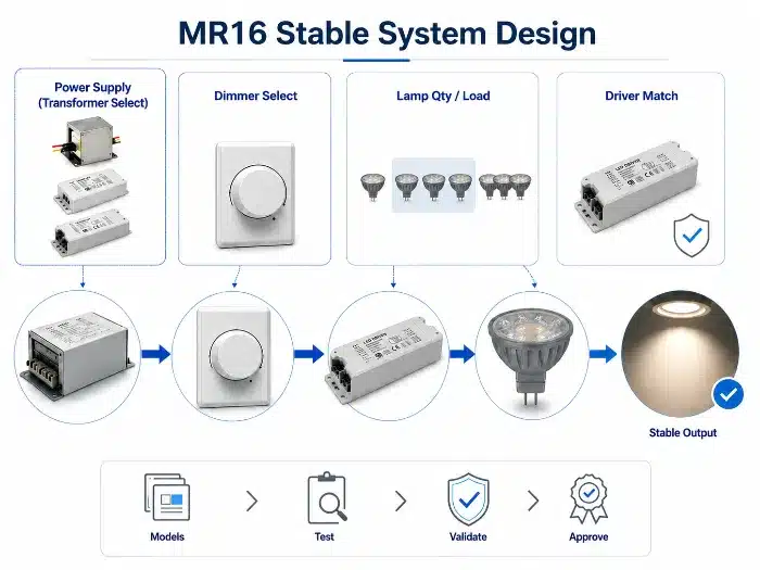
A stable MR16 system is not achieved by selecting a “compatible lamp” in isolation. Stability comes from defining the operating window of the complete channel. That is especially important in hospitality and commercial work, where maintenance access is costly and dimming performance is part of the visual standard.
If this matching work is skipped before procurement, the same budget saved on hardware is usually spent later on recommissioning and replacements.
A stable MR16 system requires compatibility across four checkpoints:
Supply type
Identify whether the source is magnetic transformer, electronic transformer, or LED driver replacement.Load window
Confirm minimum and maximum load per channel, including partial failure and staged retrofit conditions.Control waveform
Confirm dimmer type, conduction range, and whether the transformer distorts the waveform delivered to the lamp.Driver operating thresholds
Verify lamp startup threshold, hold-up behavior, protection logic, and low-end dimming stability.
The full system should be validated in a realistic sequence: apply the expected input condition, measure transformer and dimmer response, observe lamp-driver current and voltage behavior, and confirm visible output stability.
Recommended project process:
- collect actual transformer and dimmer models
- define lamp quantity per circuit
- test across expected mains tolerance and temperature range
- validate cold start, warm start, full load, and minimum load
- check dimming repeatability, not just dimming range
- lock approved batch after validation
| Design Checkpoint | 需核实事项 | Risk if Ignored | 商业影响 |
|---|---|---|---|
| 变压器类型 | Magnetic or electronic behavior | Unstable operation | Rework and troubleshooting time |
| Channel load | Minimum and maximum lamp count | Flicker or no start | Room-by-room inconsistency |
| 调光器类型 | Leading-edge or trailing-edge | Low-end failure | Scene quality complaints |
| Lamp driver thresholds | Startup and hold-up behavior | Shutdown or dropout | High maintenance call rate |
Compatibility claims should be based on a defined test matrix, not assumption. For project business, the intended transformer and dimmer schedule should be supplied before final approval so the system can be simulated under realistic electrical conditions.
MR16 stable system design transformer driver dimmer matching
When to Replace MR16 Systems with Integrated LED Solutions
There are cases where continued MR16 retrofit effort is no longer economically sound. If the project contains aging transformers, mixed dimming hardware, poor access ceilings, or strict low-end scene requirements, repeated compatibility tuning can cost more than replacing the architecture entirely.
For contractors and asset managers, this becomes a lifecycle decision rather than a lamp-selection issue.
Replacement with integrated LED luminaires or dedicated LED drivers should be considered when:
- existing transformer population is mixed or undocumented
- low-end dimming below approximately 10% is required consistently
- repeated lamp changes have not resolved instability
- ceiling access makes future maintenance expensive
- batch consistency across many circuits is essential
- project standardization is more valuable than keeping the MR16 socket format
The decision is commercial as much as electrical. When legacy architecture contains too many compatibility variables, each retrofit attempt carries uncertainty. Over time, the cost of repeated maintenance and commissioning can make an integrated solution the lower-risk choice.
Integrated LED solutions remove several unstable interfaces:
- no separate MR16 lamp-driver variation
- no legacy halogen transformer dependency
- better control over dimming electronics at luminaire level
- simpler standardization across project zones
| 特点 | MR16 Retrofit on Legacy Infrastructure | Integrated LED Solution | 项目/维护影响 |
|---|---|---|---|
| Use of existing transformers | 是 | 没有 | Retrofit cheaper upfront, riskier later |
| Control of system compatibility | 有限 | 更高 | Better long-term stability with integrated design |
| Maintenance complexity | 更高 | 降低 | Reduced fault tracing over project life |
| Batch consistency across zones | More difficult | 更简便 | Lower operational risk |
In large hospitality projects, once the electrical ecosystem becomes too fragmented, staying with MR16 is often a false economy. If multiple rounds of compatibility correction are already expected, moving to an integrated LED platform is usually the cleaner engineering decision.
MR16 replacement integrated LED solution commercial retrofit
Common MR16 LED Troubleshooting Questions
Why is my MR16 LED flickering after replacing halogen?
The most common causes are transformer minimum-load mismatch, electronic transformer instability, dimmer incompatibility, or a lamp driver that cannot remain stable under the existing waveform. The first check should be the transformer model and total connected LED load, not only the lamp itself.
Why does my MR16 LED not turn on even though the old halogen lamp worked?
Halogen lamps draw enough current to keep many legacy transformers active. A low-wattage MR16 LED may not reach the transformer’s operating threshold or the lamp driver’s startup threshold, so the circuit may show voltage but still fail to produce light.
Why does my MR16 LED buzz or make noise?
Buzzing can come from the dimmer, transformer, or lamp driver when the electrical waveform is unstable. It is often worse with incompatible phase-cut dimmers, overloaded or underloaded transformers, or mixed lamp types on one circuit.
Can MR16 LEDs work with old transformers?
Sometimes, but not automatically. Compatibility depends on transformer type, minimum load, output waveform, dimmer type, lamp-driver design, and the number of lamps on each circuit. Commercial projects should test representative circuits before bulk replacement.
Should I replace the transformer or change the MR16 LED bulb?
If the issue appears on one lamp only, check the lamp and socket first. If the same symptoms appear across a circuit or room type, the transformer, dimmer, and load condition should be reviewed before replacing lamps repeatedly.
结论:商业价值
MR16 LED compatibility issues are fundamentally system-engineering failures, not simple lamp defects. The visible symptoms – flicker instability, no-light shutdown, and dimming non-linearity – are produced by interaction between transformer operating limits, phase-cut control behavior, startup thresholds, and driver protection logic.
For commercial projects, the practical objective is clear: reduce uncertainty before installation. Proper system matching improves reliability, lowers maintenance effort, and reduces lifetime cost by preventing repeated site diagnosis, unnecessary replacements, and inconsistent room-to-room performance.
B2B工程建议
For MR16 retrofit projects, collect the transformer model, dimmer type, lamp quantity per circuit, target dimming range, and failure symptom before approving bulk replacement. For bulk MR16 retrofit projects, compatibility review should be done before replacing lamps across all rooms or circuits. TECO can help project buyers review whether the issue points to minimum-load mismatch, transformer behavior, dimmer compatibility, or lamp-driver startup limits before recommending MR16 LED products or a broader 照明灯具 replacement strategy.
脚注
Phase-cut dimming: a control method that reduces delivered power by cutting part of each AC waveform, commonly implemented as leading-edge or trailing-edge dimming. PNNL’s DOE GATEWAY report explains why LED phase-cut dimming depends on dimmer, driver, and load compatibility. See PNNL: Dimming LEDs with Phase-Cut Dimmers. ↩ ↩
LED driver: the internal electronic circuit that converts incoming electrical power into controlled current or voltage suitable for LED operation. In MR16 retrofits, the driver must operate through the transformer and dimmer environment, not only under clean bench power. ↩
Non-linear load: a load whose current draw does not follow the input voltage proportionally across the waveform. Analog Devices explains that MR16 LED lamps and halogen MR16 lamps draw current differently, which can prevent stable operation with many electronic transformers. See Analog Devices: MR16 LED Driver Compatibility. ↩
Minimum load threshold: the lowest connected load at which a transformer or dimmer can regulate and operate correctly. DOE guidance on LED MR16 replacement lamps notes that low LED wattage may not meet the minimum-load requirement of transformers designed for halogen MR16 lamps, causing shutdown or flicker. See DOE: LED MR16 Lamps. ↩
Magnetic transformer: a conventional iron-core transformer that converts voltage through electromagnetic induction at line frequency. Its behavior differs from high-frequency electronic transformers, so MR16 LED compatibility should be evaluated by transformer type rather than voltage label alone. ↩
Hold-up threshold: the minimum stored energy or input condition required for a driver to remain in stable operation between waveform interruptions. ↩
Leading-edge dimming: a phase-cut method that removes the front portion of each AC half-cycle, commonly associated with triac-based dimmers. NEMA SSL 7A addresses phase-cut dimming compatibility requirements for LED systems. See NEMA SSL 7A phase-cut dimming compatibility summary. ↩
Trailing-edge dimming: a phase-cut method that removes the end portion of each AC half-cycle, typically offering better compatibility with electronic LED loads. Compatibility still depends on the full chain of dimmer, transformer, lamp driver, load count, and wiring conditions. ↩